|
|
There are two types of panels available in Vehicle Simulator, the onscreen panel and the vehicle panel, the onscreen panel can be seen pressing P, the vehicle panel is part of the the vehicle itself and is seen inside the cabin. You can use any type of panel you wish, pressing Control + P shows available panel options for the onscreen panel.
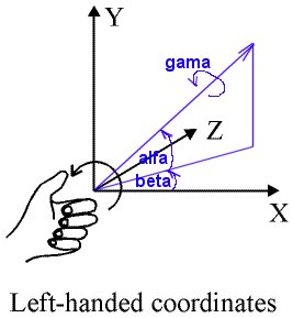
The Coordinate System:All positions and angles of vehicle parts and panels in Vehicle Simulator are measured in a left hand coordinate system, positions are given in meters, angles are given in radians ( 1 Radian = 57.295 degress ).
The On Screen Panel:For every type of vehicle there is a different type of panel seen on screen, this type is defined by a file in the panels directory of the program. This file contains the name, position and scale of panel used for each type of vehicle, for example these are the contents of the file plane.cfg inside the panels directory.
The panel parameters are:
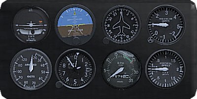
The first parameter is the name of the panel to use when this type of vehicle is loaded, this name points to a directory inside the panels directory, where the panel structure is defined. The other parameters are the panel scale, x,y,z position, and angles of
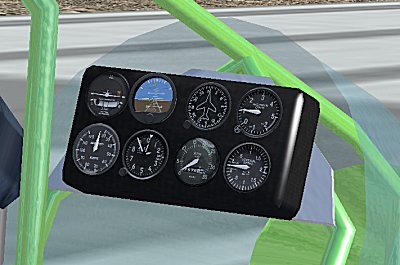
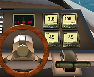
rotation. Except for the name of the panel, the other parameters are optional, when missing, default values are used. A typical onscreen panel can be seen in the image below. The Vehicle Panel:Inside the vehicle.cfg there are optional parameters defining the type and position of panel inside the vehicle's cabin, are measured from the origin of the vehicle, for example this is a part of the vehicle.cfg of the Aerolight vehicle.
The panel parameters are:
The first parameter is the name of the panel to use when this type of vehicle is loaded, this name points to a directory inside the panels directory, where the panel structure is defined. The other parameters are the panel scale, x,y,z position, and angles of
rotation. Except of the name of the panel, the other parameters are optional, when missing default values are used. A typical vehicle panel can be seen in the image below.
The Panel Configuration File:Each directory inside the panels directory of the program contains a panel structure, this file is called panel.cfg, a typical panel file looks like this:
The first parameters of this file give the position and scale of the panel, and the number of instruments in it, the following lines give instrument name, position, orientation angles and scale for each instrument, these parameters are optional, when missing default ones are used. The panel parameters are:
The instrument parameters are:
The Panel Mesh FileThe panel can have also a 3D mesh file for the part in which instruments are placed, this file is called panel.x, this file and attached textures are also placed inside the panel directory.
Instrument TypesThere are many instrument types in Vehicle simulator, some have functions suitable for specific vehicle types, for example when a radar instrument is used, the vehicle type used determines the type of radar used, marine or airborne. Instruments have four basic types:
Instrument names determine their function, the name is checked against the list of tags below and the instrument type is set, the following table shows the available instrument tags and their function.
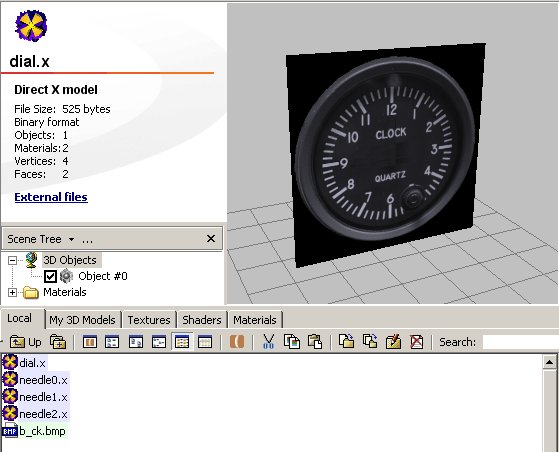
Analogue Instruments:Most of the instruments used in panels are analogue, this means that they have a dial and several needles, each needle measures some value between a minimum and maximum value, and rotates between a minimum and a maximum angle. For every instrument there is a directory inside the instruments directory of the program, inside the instrument structure file called instrument.cfg, a typical instrument file looks like this:
The first parameters of this file give the number of needles in the instrument, the following lines give the position of the needle and the measured limits for the needle and rotation angles for these limits. Analogue instrument parameters:
A typical analogue instrument looks like the image below.
Digital instruments:some of the instruments have digital counterparts as well, these give a simple digital reading of one or more value, and show it against the dial of the instrument in a given font and color. For digital instruments the parameters have a fixed format, this is a typical sample of such instrument.
Digital instrument parameters:
A typical digital instrument looks like the image below.
The Instrument Mesh FilesThe instrument can have also a 3D mesh file for the part in which needles are placed, this file is called dial.x, this file and attached textures are also placed inside the instrument directory, there are also 3D mesh files for each needle, called needle1.x, needle2.x, etc..
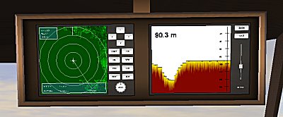
Screen Instruments:Some of the instruments require a specific screen with several button and specific display, such instruments include the MAP, the GPS, the marine RADAR, the airborne RADAR, the Echo Sounder, the Radio Navigation settings and the Auto Pilot settings. These instruments do not have a directory inside the instruments directory and not have any mesh parts, the name of the instrument is fixed, and is used along with its position and scale to place this instrument upon the instrument panel. A typical screen instrument looks like the image below.
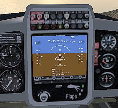
DLL Instruments:The most powerful aspect of Vehicle Simulator instrument panel is the ability to connect custom made instruments and panels to it, this is done using a specific DLL and drawing into a device context it provides. The DLL has a structure which is filled by the program in runtime, and a device context in which the DLL draws, alternatively you can create your own custom window and draw into it instead. This DLL is written in C++, the source file is given inside the DLL_G1000 instrument directory of the program, the documentation of this DLL is given inside it for the benefit of users who would like to expand this DLL into their own instrument or panel. A typical DLL instrument looks like the image below.
|